|
When I started building my induction coil, looking around for
information, revealed a bunch of practical information (- a number of books,
written on the subject! - ), but no applicable, up to date "engineering
theory" about the "obsolete device: induction coil". The knowledge
about the subject, probably available in the automotive industry, is not
within reach for me. So..., I made my coil based on the traditional
information, but kept in mind, the situation was not very satisfactory, from
the theoretical viewpoint. The practical implication of this defect is: in
designing modern versions of an interruptor, the designer is missing
data, in order to size the semiconductors utilized, regarding voltage, current,
(+ their time derivatives dV/dt, dI/dt) and power. The problematic part of
the old induction coils beeing the interruptor (- from Wagner's Hammer, Mercury-Rotating
Interruptors, to Wehnelt Electrolytic Breakers - ), the modern power-electronic
devices offer a most attractive alternative: being it traditional style interruption
of a DC-loaded primary, or an alternative capacitor discharge(-speak: dimmer-)
device. But many semiconductors are sent to "HV-heaven", just because of
inadequate knowledge of the environment, where to operate them. An, even
rudimentary, theory of the induction coil, allowing the simulation of the
most important behavior of the coil, would be most welcome. The
decision, I took, was to follow the traditional line of a DC-interruptor,
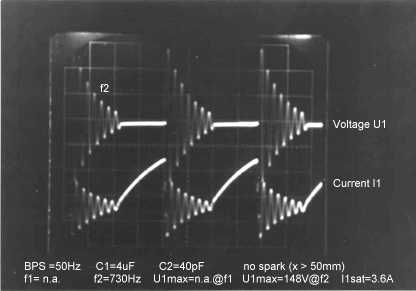
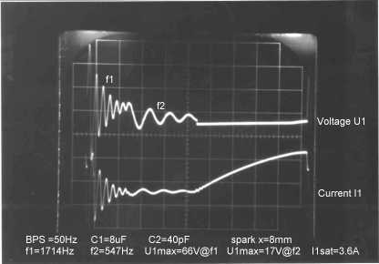
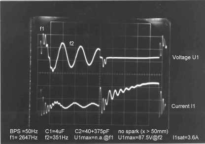
for my coil testing. In order to gain an experimental base for modelling,
34 careful measurements
were planned and carried out in November 2001.
click to see the
induction coil's main data
On Dec. 23rd, 2001, I wrote: "This page
is not yet finished; please have a look again in a few weeks."
Sorry, but I got stuck with the further development of "my"
theory, which is based on the one of A.Bouwers, in his book "Elektrische
Hoechstspannungen", Springer Berlin, 1939, pages 33 to 36 (Bouwers's text
is downloadable as
IndukBow.zip
- 462kB -, containing .gif files of his text).
I also rederived his theory, in order to gain a better
understanding (please contact me, if you like to see the 14 page handwritten
derivation), finding some very few little errors. Then I tried to apply the
theory to my experiments, by means of an Excel-spreadsheet: Well,...while
is was a part success to explain the dominant 2 frequencies of the coil,
I failed to generate the waveforms of my measurements, because the theory
is for the lossless case only, and induction coils exhibit relatively
high losses! Even the beginning of the waveforms didn't match the measured
ones, which I was erronously expecting. And Bouwers's theory is never considering
the spark as an element to take in account for modelling. Though, the modest
semiempirical formulae below serve as a vehicle to correlate simple measured
frequencies to coil parameters. .
|