|
|
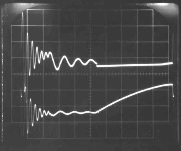
| Operating the inductor with 8 mm secondary-spark.
The
sparking time is adapted to the experiment (3.2ms; sorry: no predictive
way!). The breakdown voltage of the sparkgap was estimated by a first simulation
run without spark (breakdown voltage set to DC=1000kV), then reading the
first peak of U2~22.5kV, then setting DC=22kV. The log-decrement of the
oscillations is dominated by the value of the "iron resistor" Rfe,
which, within reasonable limits, regarding results from 50Hz "transformer
tests", was looked at, as a fitting parameter for the damping behavior
of the oscillations. The simulation result, giving a qualitatively satisfying
representaton of the experiment, is not yet really satisfactory, because
of:
1.) Simulated voltage U1 too high ( i.e. U1max = 94V(sim.) vs. 66V(exp.)
)
|
 |
|
| Simulated Waveform | Waveform Photo 33A |
 |
 |