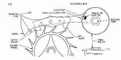
 Fig. V. English lever
LEPINE CALIBRE. A watch movement in which the top plate is replaced by bars or bridges. Introduced by J.
A. Lepine in about 1770. This layout made possible a much thinner watch, particularly with countersinks in the
dial plate and a hanging going barrel.
LEVER ESCAPEMENT. Basically, an escapement in which impulse is imparted to the balance by means of a
lever, having at one end a pair of pallets which engage with the teeth of the escape wheel, and at the other a fork
with a notch, into which the impulse pin on a roller fixed to the balance staff enters, receives impulses from the
lever, and exits. The lever escapement can be divided into two main forms: the English with pointed escape wheel
teeth, and the continental or modern Swiss form with club teeth. In the former the lift is on the pallets, and in the
latter it is divided between pallets and teeth. The action of both is fundamentally the same.
Fig. V shows the right-angled English form with single or table roller. In the last quarter of the 19th century the
double roller was used on high quality watches, the safety action provided by the dart taking place on a separate
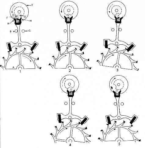
and smaller roller located below the impulse roller. The Swiss form has two rollers as seen in Fig. VI. Here, A
designates the escape wheel. B and C are
 Fig. V. English lever
banking pins: two vertical pins which limit the travel of the lever in either direction. D is the dart or guard pin. E is
the impulse roller mounted on the balance staff (not shown) and F, located on E, is the impulse or ruby pin. Below
E is the second or safety roller, also mounted on the staff, with a crescent cut away at G. H and H are the horns of
the lever. Neither the balance staff, balance nor balance spring are shown. The impulse pin F projects downwards
from the underside of the roller E and engages in the rectangular notch of the fork between the horns H and H.
The dart D, attached to the lever, is at a lower level than the horns being in the same plane as the safety roller and
crescent G.
Position 1 in the diagram shows a tooth of the escape wheel, which revolves in a clockwise direction, at rest on the
locking face of the entry pallet. The escapement is locked. The impulse pin has just entered the notch in the lever
fork. The balance must be imagined, at this moment, to be swinging in an anti-clockwise direction taking, of
course, the rollers and the impulse pin with it as it swings. The lever is at rest on the banking pin B. As the balance
continues its swing, it causes the impulse pin F to move the lever and pallets over from left to right, so releasing the
tooth from the locking edge of the entry pallet. As the tooth leaves the locking edge of the pallet it moves along the
impulse face of the pallet' giving impulse to the lever as it pushes the pallet out of its path. This is shown in 2.
The impulse given to the lever is transferred via the notch to the impulse pin, and thus to the balance. 3 shows the
position reached after this motion is completed. By the time the tooth whose movement we have been following is
clear of the impulse face of the entry pallet, the second tooth in advance of it drops on to the locking edge (on the
inner side) of the exit pallet, and the escape wheel is again momentarily held; the lever is now at rest on banking
pin C while the balance completes its oscillation, still in the anti-clockwise direction but detached from the
escapement.
When the energy delivered by the impulse and the momentum of the balance is expended, the balance spring exerts
itself by 'uncoiling', reversing the motion of the balance. In due course the impulse pin again enters the notch, from
the opposite direction from that in which it left it, as shown in 4, and the operation just described is repeated; this
time, however, the exit pallet is unlocked, and impulse is given to that pallet to assist the balance in its clockwise
motion by 'pushing' the lever over from right to left. Position 5 shows the final stage reached in the cycle, with a
tooth again locked on the entry pallet and the balance completing its swing in a clockwise direction, and detached
from the escapement.
The escape wheel teeth are so formed in relation to the pallets that the pressure of a tooth on the locking face
produces a drawing-in motion of the pallet towards the escape wheel. This is the important device of 'draw'. Its
purpose is to counteract the tendency of the lever to leave the banking pins before it is impelled to do so by the
ruby pin acting within the notch. The purpose of the banking pins is to limit the supplementary travel of the lever,
in either direction, after locking has taken place.
The object of the dart is to prevent the escape wheel being unlocked while the balance is oscillating free of the
escapement; if this were to happen, the impulse pin would come into contact with the outside of the horn and the
watch would stop. It cannot happen because if the lever is jerked by some outside cause while the balance is free,
the dart comes up against the edge of the safety roller and prevents further movement of the lever. The crescent is
cut in the safety roller to allow the dart to pass freely while the impulse pin is within the fork. The horns of the fork
are an additional safety device and may come into play while the dart is passing through the crescent and the
impulse pin is within the fork. The horns are there to act in place of the dart at that stage.

Fig. VI. Club-tooth lever
LEVER NOTCH. In the lever escapement, the opening in the fork into which the impulse pin penetrates.