|
Simulation is probably the easiest way for evaluating an induction coil. Taking losses into consideration is no more a challenge, and considerable proximity to reality may be achieved, with limited information about the coil, and lumped parameter modelling only. The main elements, needed for coil modeling, can be estimated from simple, standard transformer short- and open circuit experiments, and some "ringdown" experiment, comparable to one of the 34 measurements carried out for my coil. The transformer experiments are needed for estimating the inductances L1(primary), L2(secondary), M(mutual inductance), coupling coeff. k=M/sqrt(L1*L2), and an estimation of the copper loss resistors R1, R2, as well as the iron-loss resistor Rfe. In Jim Lux's HV-book is a good description for estimating transformer parameters, and Tero Ranta, recently(March 17th, 2001) published an easy way to assign L1, L2 and k for modeling. As an example, my own transformer Excel-workbook, applied to my induction coil, can be downloaded (in zipped form) as: Inductor_Sk.zip. (~62kB). - The "ringdown" experiment is needed, in order to estimate the secondary self capacitance C2, from observed natural frequency f2, and given capacitance C1 + coil parameters L1, L2, k (see theory page!). The ringdown experiment is also supplying the damping behavior (log. decrement) of the oscillations, and as such, giving the relevant information for "trimming" the parallel resistor Rfe, which is dominantly responsible for the damping behavior of the coil. An oscilloscope is needed for the "ringdown" test. The "sparking part" of the simulation has almost no predictive power, as mostly the case in TC coiling. I've used Gary Lau's representation of a voltage dependent switch, as a rudimentary means, to model the secondary spark, together with a 50k resistor. The time of sparking is set as some 3..msec of the one-shot module 74123; the 3...msec value beeing taken from experiment as "duration of the spark". - Setting the threshold of spark breakdown is another issue: I'm just performing a first simulation run, without spark, by setting the breakdown voltage to ~1MV. Then, reading the secondary voltage at the first peak, I set the breakdown voltage for the next run just slightly below that peak - not a very "scientific" practice - but, I'm not able to offer a better way currently! Probably, some of the frequently used ignition coil types, increasingly used for triggered spark gaps, might be assigned in the way above, in order to gain more knowledge about them, even if they are successfully used without all this "theoretical" background. click to see the induction coil's main data |
 |
| 3 simulation runs, for 2 experiments | |
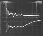 |
Experiment 24A
Version a. |
|
Experiment 24A
Version b. |
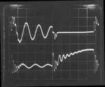 |
Experiment 33A |